
If you’re studying mirrors and their properties, chances are you’ve come across the concept of ray diagrams. These diagrams are a graphical way to depict how light rays interact with mirrors and can be used to determine the position, size, and nature of images formed by mirrors.
Understanding how to interpret and draw mirror ray diagrams is crucial in optics and can help you visualize the behavior of light rays. This skill is especially important when studying reflection and mirrors, as it allows you to predict where an object will appear in a mirror and whether it will be upright or inverted.
In this mirror ray diagram worksheet, you’ll find answers providing step-by-step explanations for various mirror configurations and scenarios. Whether you’re dealing with a plane mirror, concave mirror, or convex mirror, these answers will guide you through the process of drawing accurate ray diagrams and analyzing the resulting images.
By working through this worksheet, you’ll gain a solid understanding not only of how to draw mirror ray diagrams, but also of the underlying principles that govern mirror reflections. You’ll also develop your skills in problem-solving and critical thinking as you analyze and interpret the diagrams. So grab your pencil and get ready to dive into the world of mirror ray diagrams!
Mirror Ray Diagram Worksheet Answers
Completing a mirror ray diagram worksheet allows students to practice their understanding of how light rays behave when they interact with mirrors. By accurately drawing and labeling the incident and reflected rays, students can demonstrate their ability to apply the laws of reflection.
In the worksheet, students are typically provided with a diagram of a mirror and an object, and they are asked to draw the incident and reflected rays. The answers to these worksheets can vary depending on the specific situation, but generally, students should follow these guidelines:
- Incident Ray: The incident ray is drawn from the object to the mirror, with an arrow indicating the direction of travel.
- Normal: The normal line is drawn perpendicular to the surface of the mirror at the point of incidence.
- Reflected Ray: The reflected ray is drawn from the mirror to the point where the incident ray intersects the mirror, with an arrow indicating the direction of travel.
By accurately drawing and labeling these rays, students can determine the location and nature of the image formed by the mirror. They can analyze the size, orientation, and position of the image, as well as whether it is real or virtual.
Completing mirror ray diagram worksheets helps students develop their spatial reasoning skills and their understanding of how light behaves when reflected. It also reinforces the principles of geometry and trigonometry that underlie these diagrams. By practicing these skills, students can gain a deeper understanding of optics and the behavior of light.
Understanding mirror ray diagrams
Ray diagrams are a visual representation that helps us understand and analyze the behavior of light rays as they interact with mirrors. They are especially useful when studying reflection, as they allow us to predict and understand how an object’s image will appear in a mirror.
When creating a ray diagram, there are a few key components to keep in mind. First, we need to identify the object, which is the physical item that we want to study. Next, we draw a straight line called the principal axis, which represents the middle of the mirror. This axis is usually represented by a dotted line.
Next, we draw the reflected rays. There are two types of rays that we consider: the incident ray, which is the ray of light that travels from the object to the mirror, and the reflected ray, which is the ray of light that bounces off the mirror and travels to our eyes or another surface. These rays follow the law of reflection, which states that the angle of incidence is equal to the angle of reflection.
To draw the incident ray, we can use arrows or lines to represent the path of the light. The incident ray should start at the object and extend towards the mirror. The reflected ray is drawn by extending the incident ray backwards and showing its reflection off the mirror.
By drawing these rays and analyzing their paths, we can determine the location and characteristics of the image formed by the mirror. This includes factors such as whether the image is real or virtual, upright or inverted, and magnified or reduced in size. Understanding mirror ray diagrams is an essential skill for studying optics and can help us understand and predict the behavior of light in various situations.
Step-by-step instructions for completing a mirror ray diagram
Completing a mirror ray diagram can help you understand how light rays interact with mirrors and how they form images. This step-by-step guide will walk you through the process of creating a mirror ray diagram.
- Draw the mirror: Start by drawing a straight line to represent the mirror. Label it “Mirror.”
- Mark the mirror’s center: Find the center of the mirror line and draw a dot to mark it. Label the dot “C” for center.
- Draw the object: Decide on the location and size of the object you want to analyze. Draw an arrow or a simple shape to represent the object. Label it “Object.”
- Label the object’s position: Use a letter or a number to label the object’s position. For example, you can use “A” or “1” to mark the object’s location.
- Draw incident rays: Draw two incident rays from the top and bottom of the object towards the mirror. These rays should be parallel to each other.
- Mark the intersection points: Draw dotted lines to represent the reflected rays. The reflected rays should be drawn in a way that they appear to originate from behind the mirror.
- Mark the reflected rays: Label the points where the dotted lines intersect the mirror as “R” for reflected rays.
- Extend the reflected rays: Extend the reflected rays behind the mirror. These lines will help you locate the virtual image.
- Find the virtual image: The virtual image of the object is located where the extended reflected rays intersect.
- Label the virtual image: Label the location of the virtual image with an arrow and a letter or number.
By following these step-by-step instructions, you can create an accurate mirror ray diagram to help visualize how light rays interact with mirrors.
Common mistakes to avoid when completing a mirror ray diagram
Completing a mirror ray diagram can be a challenging task, but by avoiding these common mistakes, you can ensure accurate results and a better understanding of the principles of reflection.
1. Failing to accurately measure incident and reflected angles: When drawing ray diagrams, it’s crucial to measure the incident angle accurately. Many students make the mistake of estimating the angle, resulting in incorrect diagrams. Use a protractor or an angle-measuring tool to determine the angles precisely.
2. Not labeling the rays: Another common mistake is forgetting to label the incident and reflected rays. Without clear labels, it can be confusing to understand the direction of the rays and their interaction with the mirror. Always label the rays with appropriate symbols or letters to avoid confusion.
3. Incorrectly determining the location of the image: The position of the image can often be misunderstood, leading to inaccurate diagrams. Remember that the image formed by a concave mirror is virtual and upright if it is located between the focal point and the mirror. If the image is located beyond the focal point, it will be real and inverted.
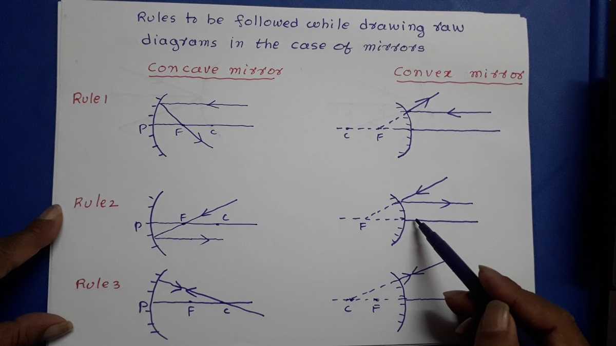
4. Confusing the terms “concave” and “convex” mirrors: Understanding the difference between concave and convex mirrors is crucial when completing ray diagrams. Concave mirrors are inwardly curved, while convex mirrors are outwardly curved. Confusing the two can lead to incorrect diagrams and a misunderstanding of how light reflects off different types of mirrors.
5. Ignoring the rules of reflection: When completing a mirror ray diagram, it’s important to remember the rules of reflection. The incident ray, reflected ray, and normal at the point of incidence should all lie in the same plane. Failing to follow this rule can result in inaccurate diagrams that do not accurately depict the behavior of light.
To avoid these common mistakes, it’s important to practice and be mindful of the key principles of ray diagrams. By taking the time to accurately measure angles, label rays, understand the type of mirror being used, determine the location of the image correctly, and follow the rules of reflection, you can ensure accurate and informative mirror ray diagrams.
Examples of completed mirror ray diagrams with explanations
Below are a few examples of completed mirror ray diagrams along with their explanations:
Example 1:
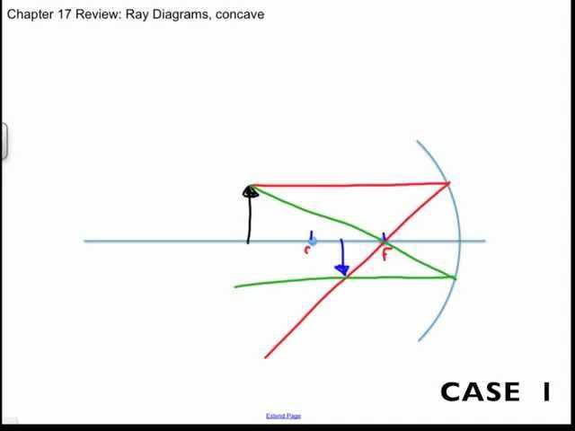
Diagram:
|
Object |
Principal Axis |
Image |
|
|
Explanation:
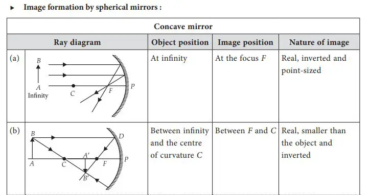
In this example, an object in the form of an arrow is placed in front of a concave mirror. The arrow is pointing towards the mirror. Using the rules of ray diagrams, we draw two rays from the tip and base of the arrow.
The first ray is drawn parallel to the principal axis. After reflection, this ray appears to pass through the focal point on the opposite side of the mirror.
The second ray is drawn through the focal point. After reflection, this ray appears parallel to the principal axis.
Where these two rays intersect behind the mirror, we find the image of the arrow. In this case, the image is an upside-down arrow located behind the mirror.
Example 2:
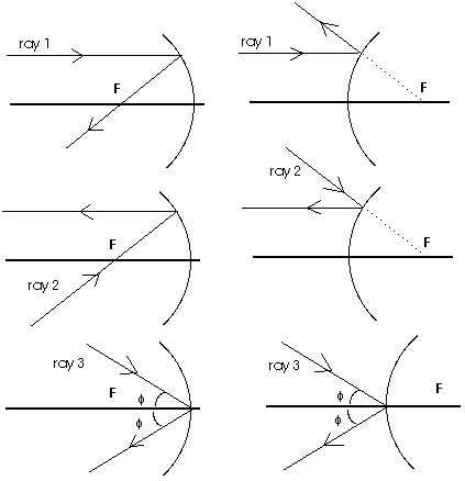
Diagram:
|
Object |
Principal Axis |
Image |
|
|
Explanation:
In this example, a small dot is placed in front of a convex mirror. Using the rules of ray diagrams, we draw two rays from the dot.
The first ray is drawn parallel to the principal axis. After reflection, this ray appears to diverge from the focal point on the same side as the object.
The second ray is drawn towards the focal point. Since the ray is already moving towards the mirror, it does not change its direction after reflection.
Where the two rays appear to converge behind the mirror, we find the image of the dot. In this case, the image is a larger dot located on the principal axis.
Key Concepts to Remember When Using Mirror Ray Diagrams
When using mirror ray diagrams to analyze the behavior of light rays reflecting off mirrors, it is important to keep in mind several key concepts that will help guide you in drawing accurate diagrams and interpreting the results.
1. Reflection Laws:
- The angle of incidence is equal to the angle of reflection.
- The incident ray, the reflected ray, and the normal to the mirror all lie in the same plane.
2. Incident Rays:
- When drawing the incident rays, remember that they travel in a straight line from the source of light to the mirror.
- The angle of incidence is measured between the incident ray and the normal to the mirror at the point of incidence.
3. Reflected Rays:
- The reflected rays also travel in a straight line and obey the reflection laws.
- The angle of reflection is measured between the reflected ray and the normal to the mirror.
4. Focal Points and Center of Curvature:
- Concave mirrors have two focal points and a center of curvature.
- Convex mirrors have one focal point located behind the mirror and no center of curvature.
5. Image Formation:
- When drawing the image formed by a mirror, remember that the image is formed by the intersection of the reflected rays.
- The image can be real or virtual, upright or inverted, and magnified or diminished, depending on the position of the object relative to the mirror.
6. Ray Diagrams:
- Ray diagrams are helpful tools to visualize and analyze the behavior of light rays in mirror systems.
- Start by drawing the mirror and the object, and then use multiple incident rays to determine the path of the reflected rays.
- The intersection of the reflected rays will give you the position and characteristics of the image formed by the mirror.
By keeping these key concepts in mind and practicing with mirror ray diagrams, you will become more proficient in understanding and predicting the behavior of light in mirror systems.